To address the limitations of sensors’ obtaining reliable and long-term load measurement results, IEC developed a cutting-edge integrated monitoring and control system, featuring in-situ calibration capabilities and adaptive internal force control, allowing for more accurate and dependable measurements, even under varying conditions.
Mechanical structure of SMARTZ
IEC has SMARTZ systems for bearings, cables and bolts.


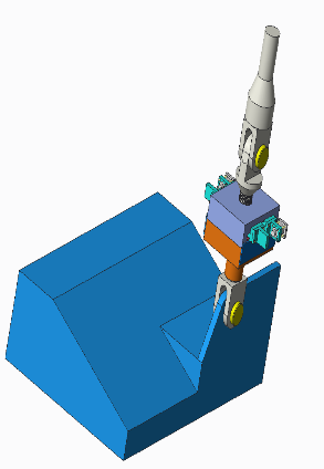
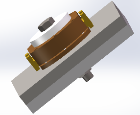
BearingSmart CableSmart BoltSmart
Core functions and mechanism of BearingSmart system
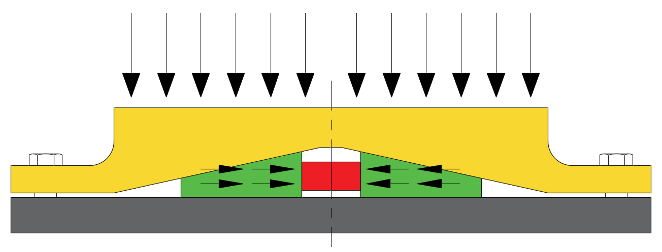
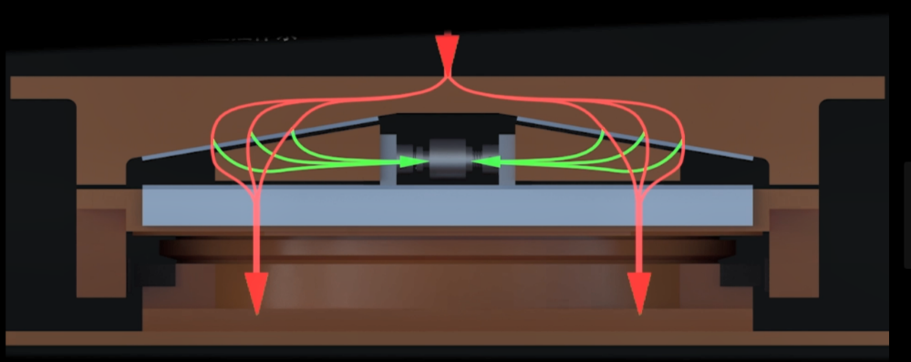
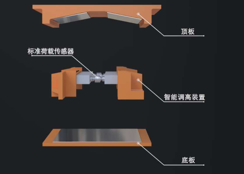
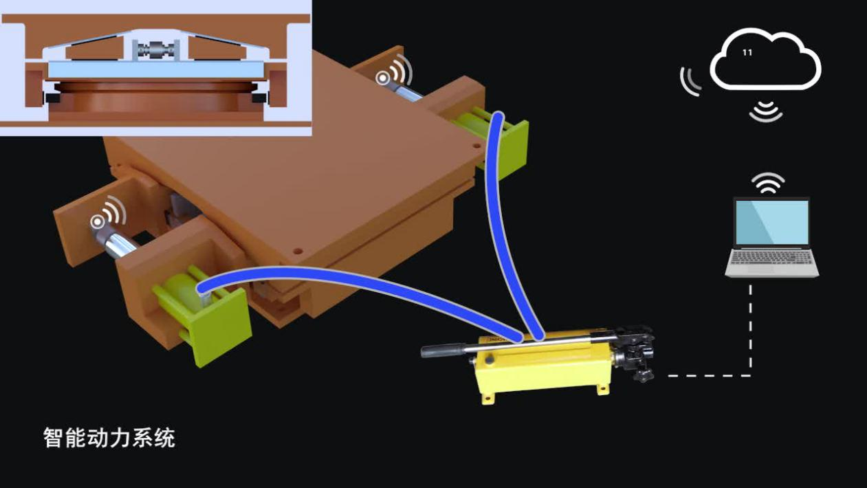
illustration to explain how BearingSmart works
1. Versatile Compatibility: The Bearingsmart system can be used in combination with any type of bearing, replacing conventional concrete bearing pads.
2. Load Redirection: Vertical forces are redirected horizontally and monitored by a much smaller horizontally arranged load cells.
3. Load Monitoring and Sensor Calibration: Vertical load is simultaneously calculated using horizontal load cells’ readings. When the sensor requires calibration or replacement, a controlled jack can be applied to push the wedge blocks apart, enabling the load cell to be recalibrated. This process can be performed without affecting the load state and height of the Bearingsmart system.
4. Formula Updating: The calculation of vertical load involves the angle of the wedge blocks (which remains constant over time), the horizontal sensor reading, and the friction. Although drift caused by temperature and moisture can be corrected, the long-term change in friction coefficient needs to be addressed. Bearingsmart's calibration not only focuses on the sensor itself but also maintains the traceability chain by updating the formula.
On-site calibration (core technology)
This process utilizes a dynamic system (wedge blocks equipped with mechanic power) to establish a new balance of internal forces within the load monitoring device, allowing for an update to the formulaic relationship between load and sensor readings using computational algorithms. The integrity of the structure's internal forces is maintained during the entire calibration process.
Downward equilibrium state
A vertical load applies to the top plate and pushes the wedge blocks moving inwards. The load cells will record the horizontal force T.
Upward equilibrium state
when calibration is needed, a controlled pair of jacks push the wedge blocks moving outwards. A control system makes sure that without significant raise of the height of the BearingSmart system (below 0.01mm), the vertical force stays the same, but the movement trend of wedge blocks reversed. The friction coefficient between the plates and wedge blocks stays the same, but the friction forces are fully reversed. The load cells integrated in jacks record a different horizontal force T'.
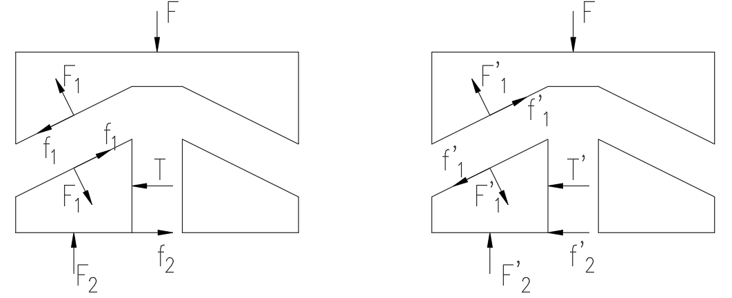
Downward equilibrium state Upward equilibrium state
Figure 7. Two equilibrium states
Under downward equilibrium state:
 (1)
(1)
Under upward equilibrium state:
 (2)
(2)
Whenμ≤0.03, tanθ≤0.2 :
 (3)
(3)
 (4)
(4)
T’—— Force sensor reading in upward state
T —— Force sensor reading in downward state
F —— Vertical load
μ —— Equivalent coefficient of friction
θ —— Slope of wedge block
By simplifying formula (3), the error between calculated F value and theoretical value is less than 0.1%.
Applying the above method eliminates the main uncertainty of force measurement and calculation. Therefore, BearingSmart system can achieve high precision force measurement and on-site calibration. In addition, the calibration process does not need to lift the main structures that is costly and may create uneven load distribution, which allows the structures in full service.
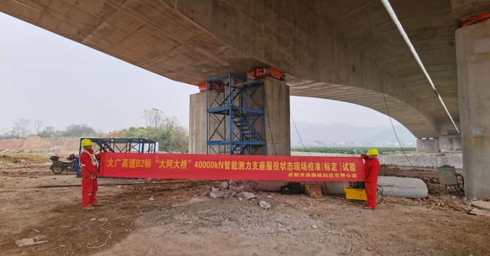
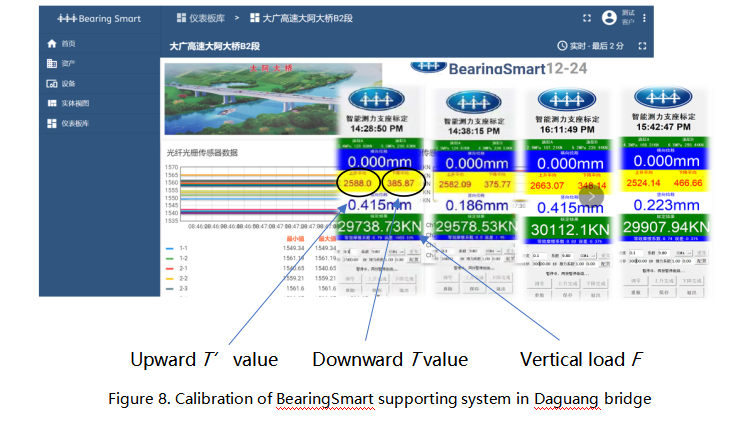
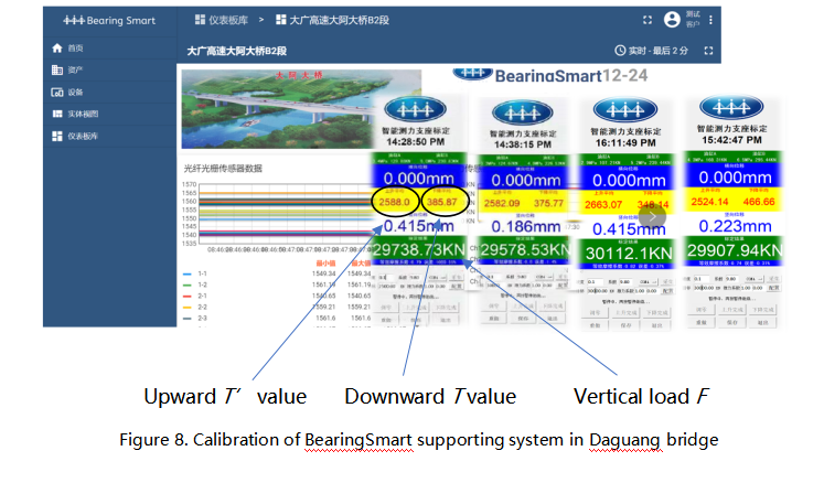
As shown above, in Daguang bridge project (continuous beam bridge), IEC engineers carried out the on-site calibration for BearingSmart integrated with a 40mn steel spherical bearing. The repetition error is less than 1%, and a pair of 200T jacks was used to provide the horizontal force to complete the on-site calibration.
(3) Self-adaptive system by BearingSmart
With the ability to on-site calibrate and therefore reliably reflect the internal forces of structures, digital-twin algorisms of internal force can be realized in SHM systems. Intelligent control of structural internal force distribution becomes feasible. For example, when BearingSmart is integrated with bridge bearings, firstly, the system can continuously monitor the reliable bearing loads of all supports. Secondly, when an uneven load distribution happens, the BearingSmart system can automatically adjust the heights of the supports by moving the wedge blocks to adaptively maintain the load distribution to an optimized level.
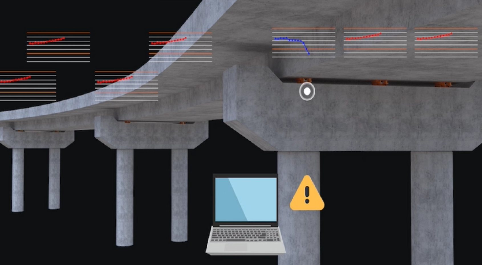
Figure 9. BearingSmart provides self-adaptive system on bridge
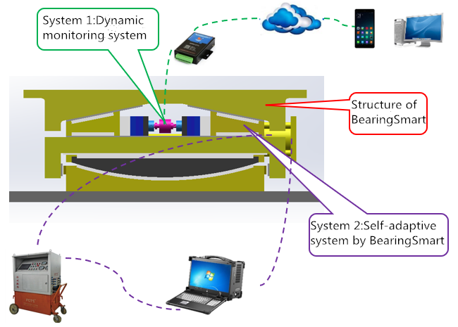
Figure 10. BearingSmart: reliable monitoring, adaptive control and digital control system
BearingSmart system can collect the real-time force data and upload it to the cloud. Internal force distribution related structural safety risks can be detected in time and corrected. Thus, the overturn risk of the bridge will be greatly reduced. This provides a new generation of digital-twins structural active safety technology.

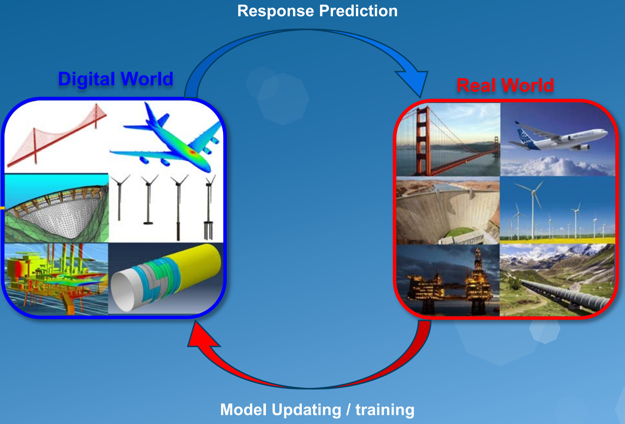
Figure 11. Digital twins of structural safety


