We use cookies to enhance your experience. Read our policy so you can understand the types of cookies we use, the information we collect using cookies and how that information is used.Privacy Policy
Close
Confirm choices


Friction Pendulum Bearings (FPB) consist of two or more horizontal steel plates with a unique shape that enables them to slide over each other, along with an articulated slider. These bearings are typically positioned between the base of a superstructure and its foundation, such as columns or piers.
Details
Friction Pendulum Bearing
1. Description of FPB
Friction Pendulum Bearings (FPB) consist of two or more horizontal steel plates with a unique shape that enables them to slide over each other, along with an articulated slider. These bearings are typically positioned between the base of a superstructure and its foundation, such as columns or piers.
The primary purpose of FPBs is to provide high stiffness and strength to support vertical loads and carry the weight of the superstructure. However, their sliding capability allows them to effectively accommodate seismic movements through the coordinated action of the FPB system. The spherical surfaces of the bearings can be designed to facilitate extended sliding by carefully selecting the radius of curvature of the concave surface.
Prior to a seismic event, FPBs function similarly to conventional spherical bearings. During an earthquake, shear pins (also known as fuses) within the bearing break, enabling sliding between the spherical surfaces and effectively isolating the superstructure from its foundation. This sliding motion converts some of the earthquake's kinetic energy into potential energy and dissipates it as heat through friction damping. As a result, the impact of earthquake forces can be significantly mitigated. After the seismic activity subsides, the re-centering property of the FPB allows it to return to its normal working state.
2. FPB design principle
The design of Friction Pendulum Bearings (FPB) is not solely influenced by the mass of the superstructure. The damping characteristics are primarily determined by the sliding action between stainless steel and the mating sliding material. Modified PTFE, a material with a higher friction coefficient compared to virgin PTFE or UHMWPE, is often used to allow for increased energy dissipation in the form of heat.
One advantage of FPBs is that the center of the bearing naturally aligns with the supported structure, minimizing torsional effects. In the case of triple sliding FPBs, there are three distinct radii that can be optimized to enhance performance for different types of earthquakes. This means that the period, vertical load capacity, damping ratio, lateral stiffness, movement, and uplift resistance force can all be independently designed without significant interdependencies.
By decoupling these design parameters, FPBs offer greater flexibility and precision in tailoring their performance to specific project requirements and seismic expectations.

An illustration explaining how FPB works during earthquake
3. Main components of FPB
The following schemes illustrate the normal designs of FPB, single sliding and double sliding with the same or different radius of the base plate and the top plate. For doubel-sliding FPB, slider moves in 2 identical concave plates-top and bottom, so larger movement, compared with single-sliding FPB, can be achieved while the outer dimensions can be reduced or increased based on design requirement.


A single-sliding PFB A double-sliding FPB

A break-up structure of a double-sliding FPB (one of the common designs)
4. Material specifications
All main steel parts of FPB shall be with a nominal yield strength of 355MPa, Q355 in Chinese standard which is equivalent to ASTM A709 Gr50, S355 in European standard.
Stainless steel is to be in accordance with GB/T 3280 06Cr19Ni10, which is equivalent to ASTM A240/A240M Type 304 with a surface finish better than or equal to 0.2μm and typical thickness to be 2.0mm.
Modified PTFE are used in FPB. The properties for Modified PTFE (M-PTFE) with and without lubricant are shown in below.
Properties of M-PTFE with lubricant
Items | M-PTFE | |||
Density ρ(g/cm3) | 2.0<p≤2.10 | |||
Tensile strength(MPa) | ≥21 | |||
Elongation at break(%) | ≥300 | |||
Ball indentation hardness H(H132/60)(MPa) | 26.4≤H≤39.6 | |||
Tensile modulus of elasticity Et(MPa) | 600≤Et≤900 | |||
Friction coefficient with stainless steel plate | Initial static friction coefficient μs | Compressive stress(MPa) | 45 | |
Relative sliding speed(mm/s) | 0.4 | |||
Temperature conditions(°C) | 23±2 | ≤0.012 | ||
0±2 | ≤0.018 | |||
-35±2 | ≤0.035 | |||
Dynamic coefficient of friction μd | Compressive stress(MPa) | 45 | ||
Relative sliding average velocity(mm/s) | 15 | |||
Temperature conditions(°C) | 23±2 | ≤0.005 | ||
0±2 | ≤0.012 | |||
-35±2 | ≤0.025 | |||
Line wear rate of friction with stainless steel plate | Compressive stress | 45 | ||
Temperature conditions | 23±2 | |||
Relative sliding average velocity | 15 | |||
Relative reciprocal sliding distance | ±10 | |||
Cumulative sliding distance | 50 | |||
wear rate | ≤5 | |||
Deformation due to vertical load compression | Compressive stress | 120 | ||
Temperature | 35±2 | |||
Load holding time | 48 | |||
Compression deformation | ≤0.0005S0 | |||
Note:S0 is the initial exposed height of the specimen. | ||||
For the thickness of more than 2mm of the slide, the tensile strength and elongation at break of the specimen made by turning method should not be less than 90% of the value specified in the table | ||||
Properties of M-PTFE sheets without lubricant
Items | M-PTFE | |||
Friction coefficient with stainless steel plate | Initial static friction coefficient μs | Compressive stress(MPa) | 45 | |
Relative sliding speed(mm/s) | 0.4 | |||
Temperature conditions(°C) | 23±2 | ≤0.007 | ||
0±2 | ≤0.008 | |||
-35±2 | ≤0.10 | |||
Coefficient of dynamic friction μd | Compressive stress(MPa) | 45 | ||
Relative sliding average velocity(mm/s) | 15 | |||
Temperature conditions(°C) | 23±2 | ≥0.005 | ||
0±2 | ≥0.006 | |||
-35±2 | ≥0.008 | |||
Line wear rate of friction with stainless steel plate | Compressive stress | 45 | ||
Temperature conditions | 23±2 | |||
Relative sliding average velocity | 15 | |||
Relative reciprocal sliding distance | ±10 | |||
Cumulative sliding distance | 10 | |||
wear rate | ≤10 | |||
Deformation due to vertical load compression | Compressive stress | 120 | ||
Temperature | 35±2 | |||
Load holding time | 48 | |||
Compression deformation | ≤0.0005S0 | |||
5201-2 premium grade silicone grease shall be used, which is in accordance with requirements stipulated in EN 1337-2.

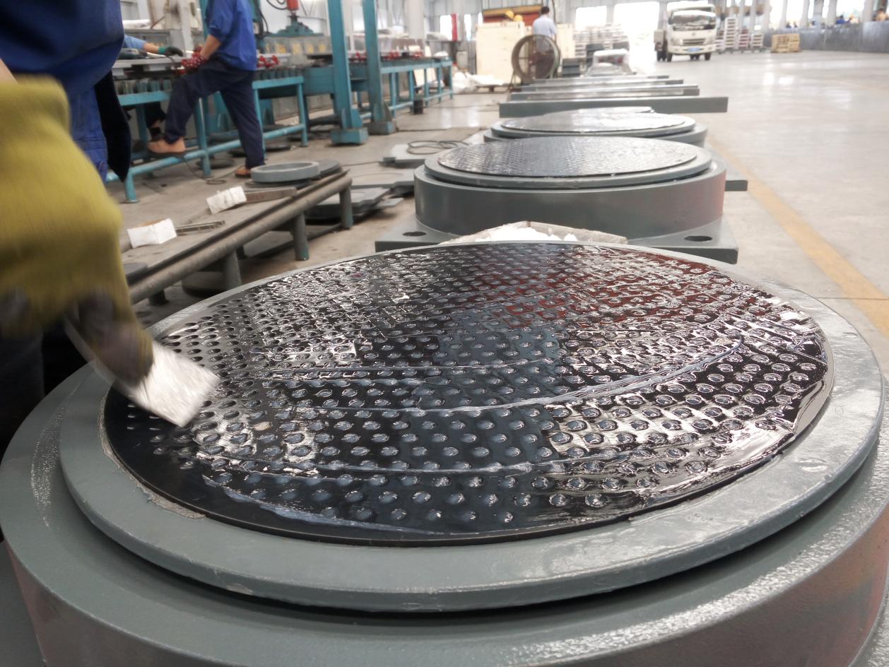
Modified PTFE are used for FPB at IEC workshop

5201-2 grease is used

IEC supplied 212 sets of FPBs for Linyi 2ed people’s hospital in Shandong, China
5. Design guidance info.
5.1 Calculation of the center angle of the rotating plate
During the horizontal sliding movement of Friction Pendulum Bearings (FPB), an important consideration is the increase in horizontal force due to the inherent horizontal stiffness of the bearing. This leads to a growing eccentricity of the force on the rotating wear plate. Unlike the fixed center angle δ (as shown in Figure 2) of the rotating wear plate in spherical bearings, which is typically set between 15.0° and 17.5°, corresponding to a 2δ range of 30° to 35°, the value of δ for FPBs requires careful consideration.
In the case of FPBs, a larger value of δ results in a more uniform distribution of the bearing force. However, this also means the need for more material, resulting in higher costs, assembly difficulties due to larger occupied space. Therefore, when determining the value of δ for FPBs, it is crucial to strike a balance. The goal is to choose a value that meets the force requirements while minimizing the value of δ, thereby optimizing the bearing's performance in terms of material usage, cost-effectiveness, ease of assembly, and space requirements.

Sliding material center angle illustration
According to EN15129, when the vertical load Fz and horizontal load Fx are applied to the center seat plate, it is meaningful to confirm the compressive stress σ>0 on the rotating wear plate under the angle θ of the inverse of the horizontal force Fx.
The condition σ>0 holds when the following equation is satisfied:
Fx/Fy≤cosδ{3(1-cosδ)-(1-cos3δ)}/2sinδ(1-cos3δ)=h(δ)
It is important to note:
h(δ)=sinδ/4
From the structural mechanics analysis there are:
Fx=DK+μFz
K=Fz/Re
Hence:
Fx/Fz=D/Re+μ
In the formula: D is the maximum horizontal displacement; K is the horizontal stiffness of the support; Re is the equivalent radius; μ is the sliding surface friction coefficient.
In general, spherical bearings have no inherent horizontal stiffness and rely solely on the fixed horizontal force generated by friction. As a result, the ratio of horizontal force (Fx) to vertical force (Fz) in Friction Pendulum Bearings (FPBs) is noticeably larger compared to spherical bearings. Similarly, the value of δ, which represents the center angle of the rotating wear plate, is also typically larger in FPBs compared to spherical bearings.
In FPBs, δ is commonly set between 25° and 45°, or even larger, depending on the specific design requirements. This larger value of δ allows for a more substantial horizontal force and accommodates the sliding movement of the bearing during seismic events. By contrast, spherical bearings with their fixed δ angle (typically around 15.0° to 17.5°) have a more limited ability to handle horizontal forces and sliding displacement.
The increased Fx/Fz ratio and larger δ angle in FPBs are key factors that contribute to their enhanced seismic performance and ability to dissipate seismic energy through sliding and friction mechanisms.
5.2 M-PTFE sheets ultimate pressure calibration
Excessive pressure leads to loss of sliding function and also to failure or near failure of the structure, indicating that this state is the limit state , the pressure distribution σ(β) on the rotating friction plate when a vertical load Fz is applied to the center seat plate is a function related to β:
σ(β)=3/2×Fz*cosβ/πr2(1-cos3β)
When β=0, the maximum value is obtained, that is, the stress is maximum at the central position of the rotating wear plate:
σmax=σ*3*sin2δ/2(1-cos3δ)
In the formula: σ is the average pressure, which is the ratio of the vertical load Fz and the horizontal projection area A = πL2/4 of the M-PTFE sheets on its symmetry axis (In the formula L is the diameter of the vertical projection circle of the M-PTFE sheets)
f(δ)= 3*sin2δ/2(1-cos3δ)
f(δ) Offset representing the maximum pressure as a function of the half angle of a rotating M-PTFE sheets sphere (Table 5)
Ratio of maximum compressive stress to average compressive stress
δ | 10° | 15° | 20° | 25° | 30° | 35° | 40° | 45° |
f(δ) | 1.008 | 1.017 | 1.031 | 1.048 | 1.070 | 1.096 | 1.126 | 1.160 |
In general, the value of the spherical bearing δ <20°, when the pressure shift is basically negligible, the average positive pressure can be calculated directly according to the projection area of the wear plate, but the δ of FPB takes a larger value, the uneven distribution of pressure can not be ignored. In the maximum limit state to meet the conditions, by the spherical bearing four Nxd ≤ fdAr, modified to:
f(δ) Nxd≤fdAr
Nxd——Design firm bearing capacity for maximum limit state
Fd——Ultimate compressive strength of M-PTFE sheets
Ar——Reduced plane area for surface sliding,Ar=γA;
γ——Bearing area reduction factor from bearing load deflection
γ=1-0.75πe/L(e is the total spherical offset)
5.3 Design of rotating surface of slider
The rotating surface of the slider and the surface of the M-PTFE sheets constitute the rotating frictional side which should be able to cover the M-PTFE sheets under all conditions. For the spherical bearing, only the design angle of the bearing can be considered, and the approximate calculation is
L1≥L+ 2ra + C1
L1 is the projected diameter of the slider rotation surface; r is the spherical radius of the slider rotation surface; a is the design rotation angle; and C1 is the safety constant.
For FPB, when the slider slides on the sliding plate, the slider will rotate at the same time, and its rotation angle can be approximated as
ω=L1/Re
Considering that the bearing itself has a turning angle of 0.02 rad, the angle δ' between the centers of the rotating surfaces of the ball crown liner should satisfy the condition
δ'>δ+L1/Re+a+C2
In the formula, C2 is the safety constant.
6. FPB with DP
Optionally, the FPB could be designed to include the Dissipative Pin (DP) as a measure of increasing the damping effect during the earthquake.

Section view of guided FPB with DP

Section view of free sliding FPB with DP

FPB with DP in fabrication

In-house testing of FPB with DP
Consult IEC engineers for detailed information.

Professional supplier of structural connection
Address:669, 10th Xingyuan Road, Xinjin, Chengdu, 610043, China
Telephone:+86-28-8255 2977
Mailbox:info@iec-inc.com