We use cookies to enhance your experience. Read our policy so you can understand the types of cookies we use, the information we collect using cookies and how that information is used.Privacy Policy
Close
Confirm choices
Viscous damping has been widely used as the energy dissipation mechanism of choice in abating resonant vibration in structures. Damping of Viscous Fluid Damper (VFD) for bridges and buildings is realized by the flow of low-viscosity fluid through the small openings (orifices).
Details
Viscous Fluid Damper (VFD)
Viscous damping has been widely used as the energy dissipation mechanism of choice in abating resonant vibration in structures. Damping of VFD for bridges and buildings is realized by the flow of low-viscosity fluid through the small openings (orifices).
Typical design includes piston, cylinder, viscous fluid, seal retainer, accumulator housing and mounting bracket. The piston splits the cylinder space into two chambers and the low-viscous fluid flows in and between the chambers repeatedly, along the piston rod moving in the cylinder. When the fluid passes the orifice on the piston, significant damping is generated so to dissipate the vibration energy during seismic events. Repeated back-and-forth of the piston converts the kinematic energy into the thermal energy until eventually dissipated completely along with the slow-down move of the piston.

A cut-away view of VFD
The damping force depends on the damping ratio and the velocity. The express is as follows:
F = C ∙ Vα
Where:
F is the damping force (kN);
C is the damping ratio (kN/(m/s)α);
V is the velocity of the fluid in the cylinder (m/s);
α is the velocity exponent.
C andαare 2 key parameters of a VFD. Following curves display their relationships.
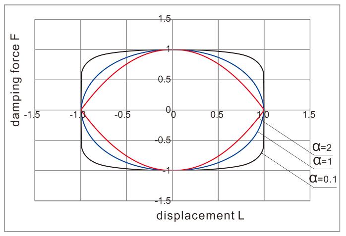
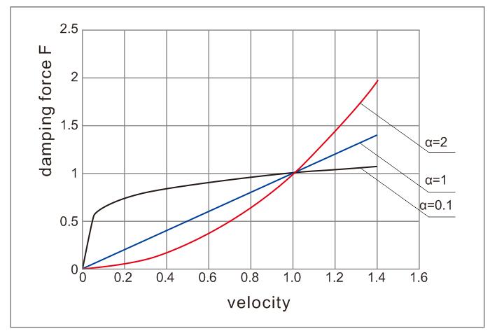
VFD curves to display the relationship between velocity and damping force F
Rigorous testing was carried out to ensure the tightness of the fluid while servicing in the cylinder, which guarantees IEC’s VFD even does not allow any level of seepage. 500,000 cycles testing verified the security of keeping the fluid. The test was done in the lab of Beijing University of Technology in Jul. 2014.
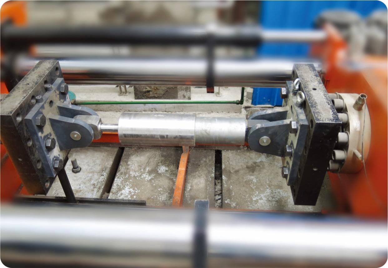
500,000 cycle tests carried out for ITT testing
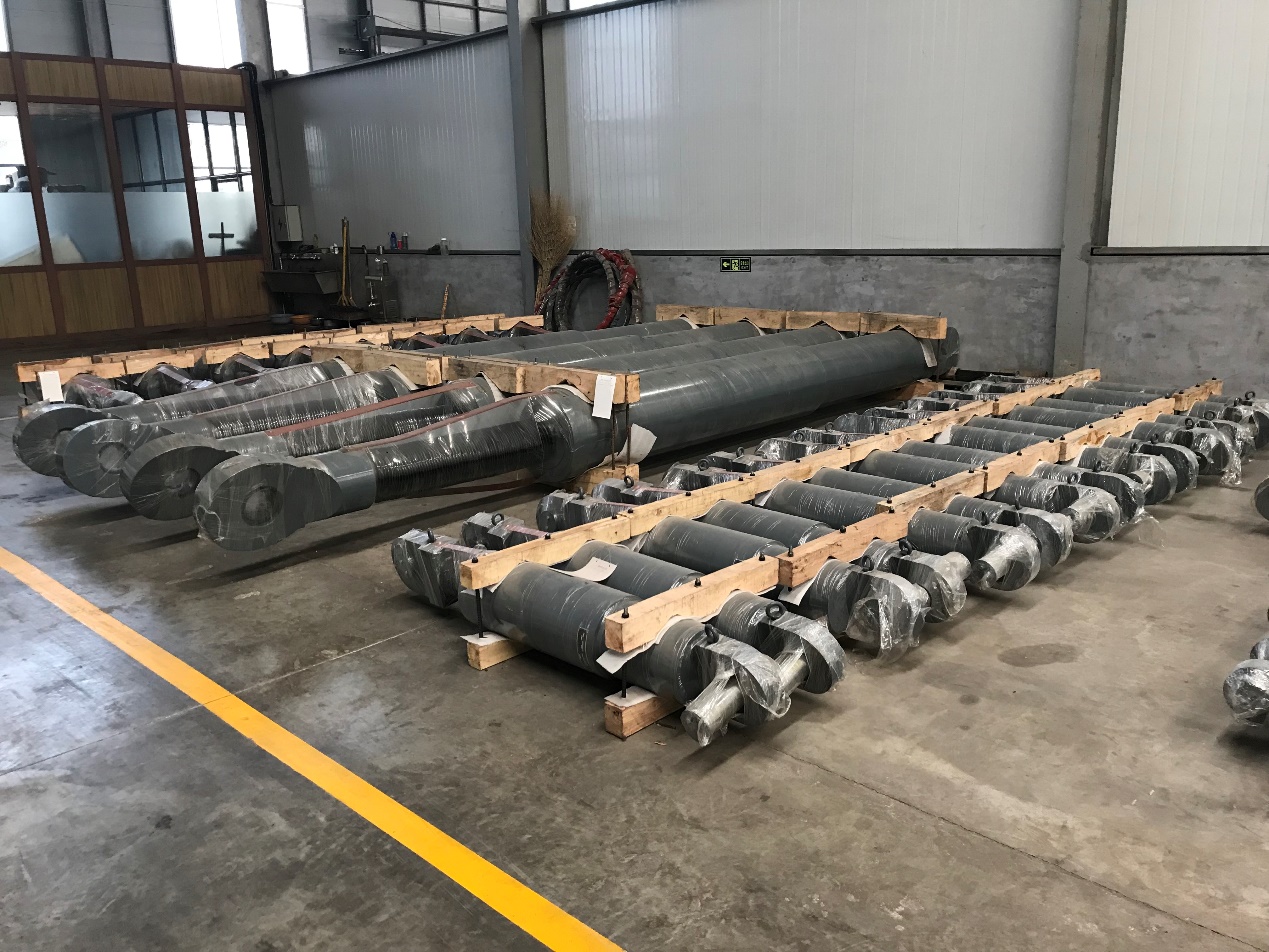
VFD prior to shipment
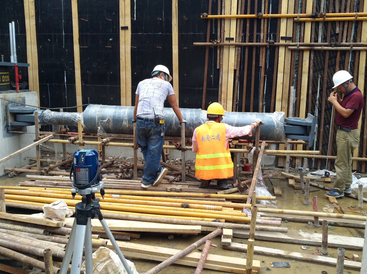
IEC VFD were installed in combination with base isolators (linear rubber bearing LNR) in all the basement of residential complex in Beijing
Denotations:
ØMax. velocity V =0.3m/s (can adapt to larger value when required);
ØMax. internal working pressure is 50 MPa;
Øα (velocity exponent) is taken as 0.04;
Øtemperature ranges from -40 ℃ to +40 ℃;
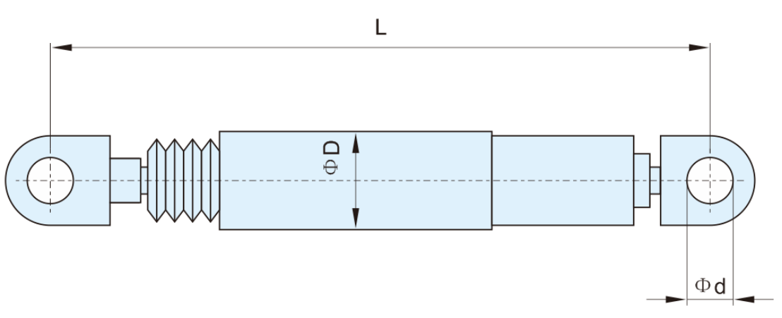
Denotations of VFD design
Consult IEC engineers for details