We use cookies to enhance your experience. Read our policy so you can understand the types of cookies we use, the information we collect using cookies and how that information is used.Privacy Policy
Close
Confirm choices
Modular Bridge Joint System (MBJS) is designed to accommodate both movement and rotation between adjacent bridge elements, while the movement exceeds the ability of a stripseal joint or a finger joint. The total movement of the bridge deck is divided among a number of individual gaps which are created by horizontal surface beams (centerbeams). In addition to supporting wheel loads, a properly designed modular joint will prevent water and debris from draining onto the underlying substructure.
Image (left) shows a 10-cell modular expansion joint in West Hongkong-Shenzhen cross-sea bridge supplied by IEC.
Details
IEC Modular Bridge Joint System (MBJS)
1. Description
1.1 General
Modular Bridge Joint System (MBJS) is designed to accommodate both movement and rotation between adjacent bridge elements, while the movement exceeds the ability of a stripseal joint or a finger joint. The total movement of the bridge deck is divided among a number of individual gaps which are created by horizontal surface beams (centerbeams). In addition to supporting wheel loads, a properly designed modular joint will prevent water and debris from draining onto the underlying substructure.
According to AASHTO LRFD Bridge Design Specification, modular joints are broadly grouped as Multiple-Support-Bar (MSB) structure, Single-Support-Bar (SSB) structure, Swivel structure (a special type of SSB structure).MBJS can be designed in a number ways to cater for different loads and movement combinations. However, due to cost concern, for normal requirement (which means there is no request of large transversal and/or vertical movement), IEC uses MSB structure for movement not greater than 320mm, which is a 4-cell modular joint. Above that, SSB structure is considered.
As per AASHTO and ETAG specifications, the max. movement per each cell is regulated to be 80mm. The entire movement of a MBJS is the nos of the cells times 80mm.
1.2 Multiple-Support-Bar (MSB) structure
MSB system have multiple support beams which are rigidly connected to longitudinal support bars. These support beams, typically referred to as centerbeams②, provide the traffic surface together with 2 beams at both sides of joint (referred to as edgebeams①) in a transverse direction. Rubber seal ③ spanning the entire lengths of those beams is locked into the preformed cavities of the beams, functioning as the watertight measures. Each support bar supports only one centerbeam. The support bars ⑦ span across the joint opening and slide between elastomeric springs ④and bearings ⑤ in support boxes to accommodate the thermal expansion and contraction of the bridge superstructure. Equidistance devices ⑧ (usually polyurethane control springs) are applied to adjacent support bar by steel retainer frame. The support boxes ⑥ are cast into concrete on both sides of the joint. For the multiple-support-bar system, a support box will hold as many support bars as there are centerbeams. According to NCHRP Report 467, the maximum numbers o centerbeams that a support box can encase is 7 (8-cell modular joint).
The MSB joints are named MML series no matter which equidistance devices are used. The value and data of MML joint are reflected in the section of “movement”.
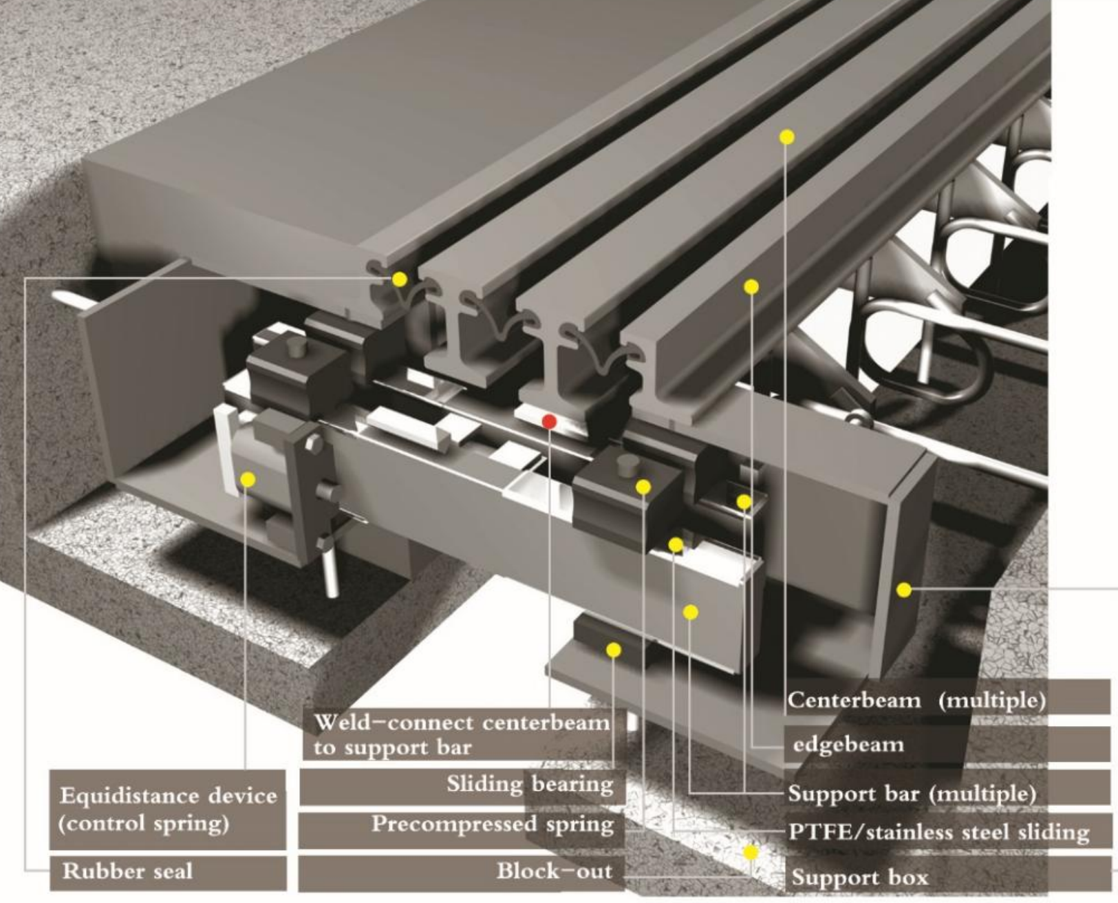
Schematic illustration of MSB structure
1.3 Single-Support-Bar (SSB) structure
SSB structure has transverse centerbeams② which are attached to support bars③ which are placed on top of stirrups (yokes)④. The elastomeric springs⑦ and sliding bearings⑧ are designed to embrace the support bar, which provide compression and sliding performance. Each support bar supports all the centerbeams. The support bars span across the joint opening and slide between elastomeric springs and bearings in support boxes⑤ to accommodate the expansion and contraction resulted from the bridge structure. Control springs are applied to centerbeams and edgebeams to work as a total kinematic system. The support boxes are cast into concrete on both sides of the joint. Rubber Seals⑥, which connect the centerbeams to others and to the joint’s edgebeams①, make the system enduringly watertight.
The SSB joints are named MZL series no matter which equidistance devices are used. The value and data of MZL joint are reflected in the section of “movement”.
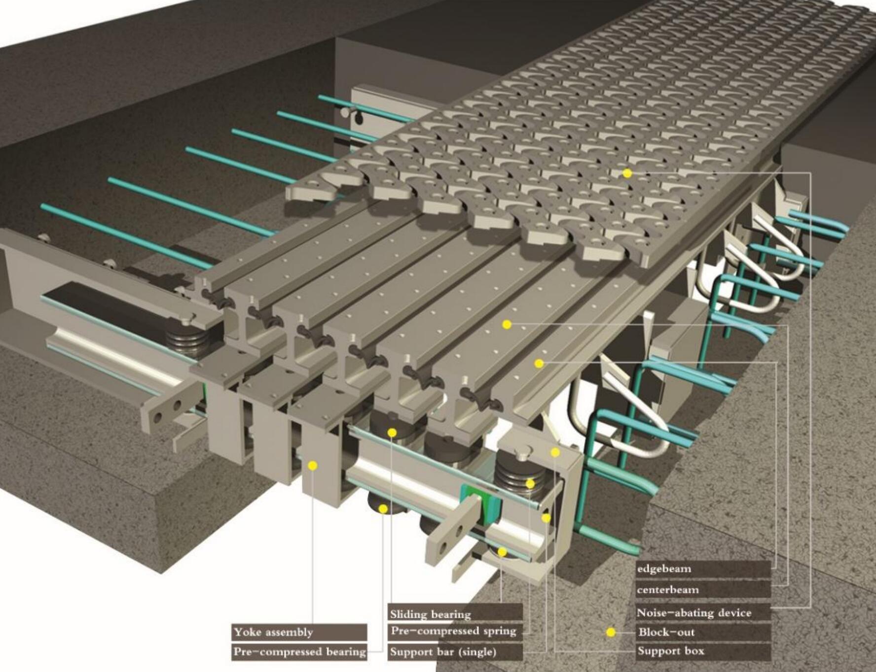
Schematic illustration of SSB structure
1.2 Transmission of wheel load
When the wheel loads starts to touch the edgebeam, they are transmitted to the assembly of anchor plate + anchor loop, which are secured in the concrete beneath the edgebeam. The support boxes connected to the edgebeams are also anchored in the concrete structure by fixing the studs. For steel bridges, the connecting method shall be prearranged to be able to fix the joint.
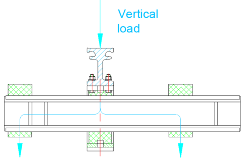
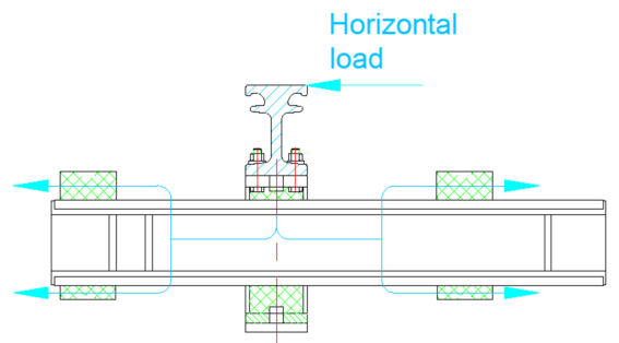
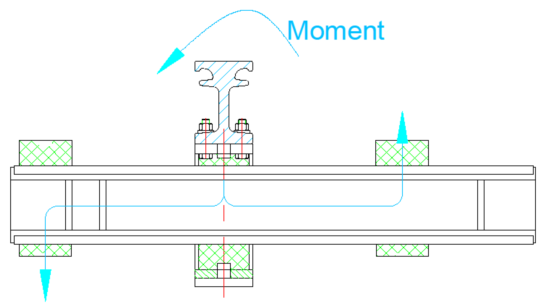
ILLUSTRATION OF HOW LOADS ARE APPLIED ON MBJS
When the wheel loads progress onto the centerbeams, simultaneously the horizontal loads are also generated. These loads are all transferred to the support bar via the rigid connection between centerbeams and support bars, then distributed to the adjacent substructure through the pre-compressed spring and bearing which have a certain rigidity. Support bars are made of solid metal and act like a continuous beam. The horizontal force is also transmitted through the elastomeric control buffer (equidistance movement).
1.3 Elastic support around the support bar
Support bar at their structure edges are elastically supported on sliding bearings which are normally elastomeric steel-reinforced bearings. The support-bar’s lift-off from sliding bearings within the support box is prevented by means of pre-stressed compression springs mounted above the support bar.
Through this elastic bearing the momentum of the wheels is damped when transferred to the absorbent elements or to the neighboring anchor assemblies. The arrangement of the elastomer bearing prevents any metal-to-metal contact and assures at the same time high damping of nosing within the vulcanized rubber elements.
The elastomeric bearing elements allow rotations in all three axes, whereby unplanned restraint forces can be prevented.
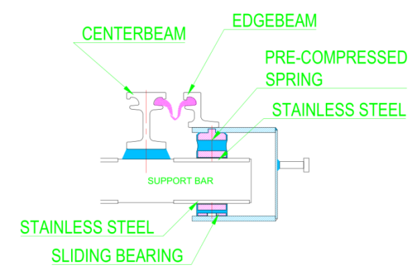

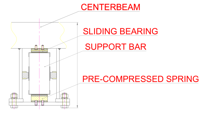
SPRING/BEARING ASSEMBLY FOR EDGEBEAM Diagram of the spring and bearing assembly beneath centerbeam BEARING/SPRING ASSEMBLY FOR CENTERBEAM
No matter for MSB structure or SSB structure, inside the support box where the support bar is beneath the edgbeam, the image (left) shows typical diagram how the spring and bearing assembly co-works to work out so the support bar slides to fulfil the movement while the support bar is “pinched” so no excessive rotation or movement in other directions are allow to occur, unless otherwise purposefully designed for.
The sliding bearing, installed right beneath the centerbeam, acts to provide sliding for the support bar when the movement comes, while the pre-stressed spring compresses against the support bar to ensure the support bar does not get loose. The stiffness of bearings and springs is complementary thus the compression due to wheel loads can be compensated through the releasing of spring. An array of such devices inside a MBJS is able to keep the support right in its working position.
1.4 Anchorage
Edgebeams are anchored with non-stretchable anchor plates and welded loops (round steels) in the concrete of the block-out. The support boxes have welded head studs to get connected to the neighboring concrete. The spacing of such anchorage is typically set at 200~250mm.
1.5 Equidistance devices
MBJS is supposed to move at its designed range the equally distributed opening at each gap. In other words, each gap shall expand or contract at the same level. To realize this, the necessary equidistance devices have to be arranged on the joint.
There are a number of different ways to achieve this. At IEC, the following 3 methods are adopted.
1.5.1 Rigid control devices
They are also named as scissor-type devices as the trellis linkages control the movement opening and closing like a scissor. This type of rigid connection works thanks to mechanical principle of the design. The metal pieces are bolt-connected along the longitudinal direction so the movement is delivered from the first set of scissor to the last.
A good thing is by this method there is no concern about the non-uniform deformations which are prone to occur in elastomeric devices. But this rigid connection devices do make a noise when the traffic passes by. Another negative factor is such rigid devices can hardly take any transversal movement and vertical deflection.
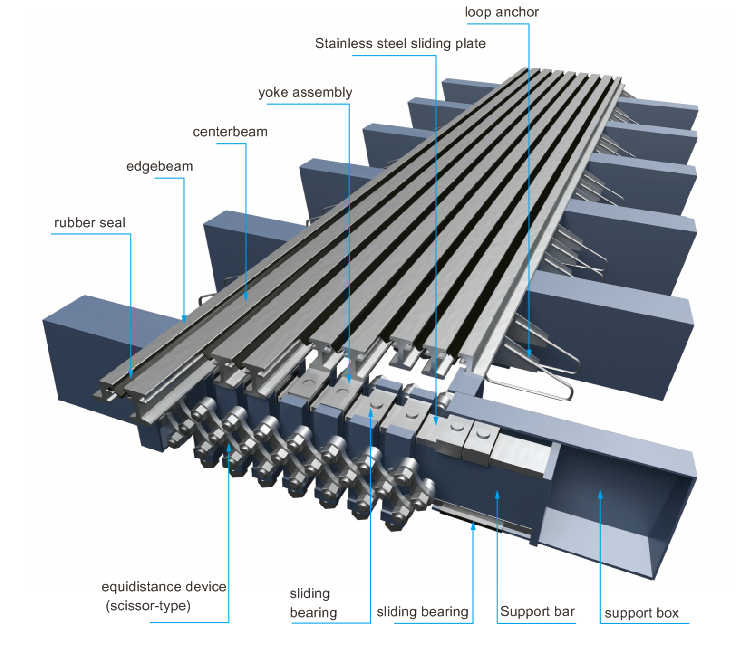
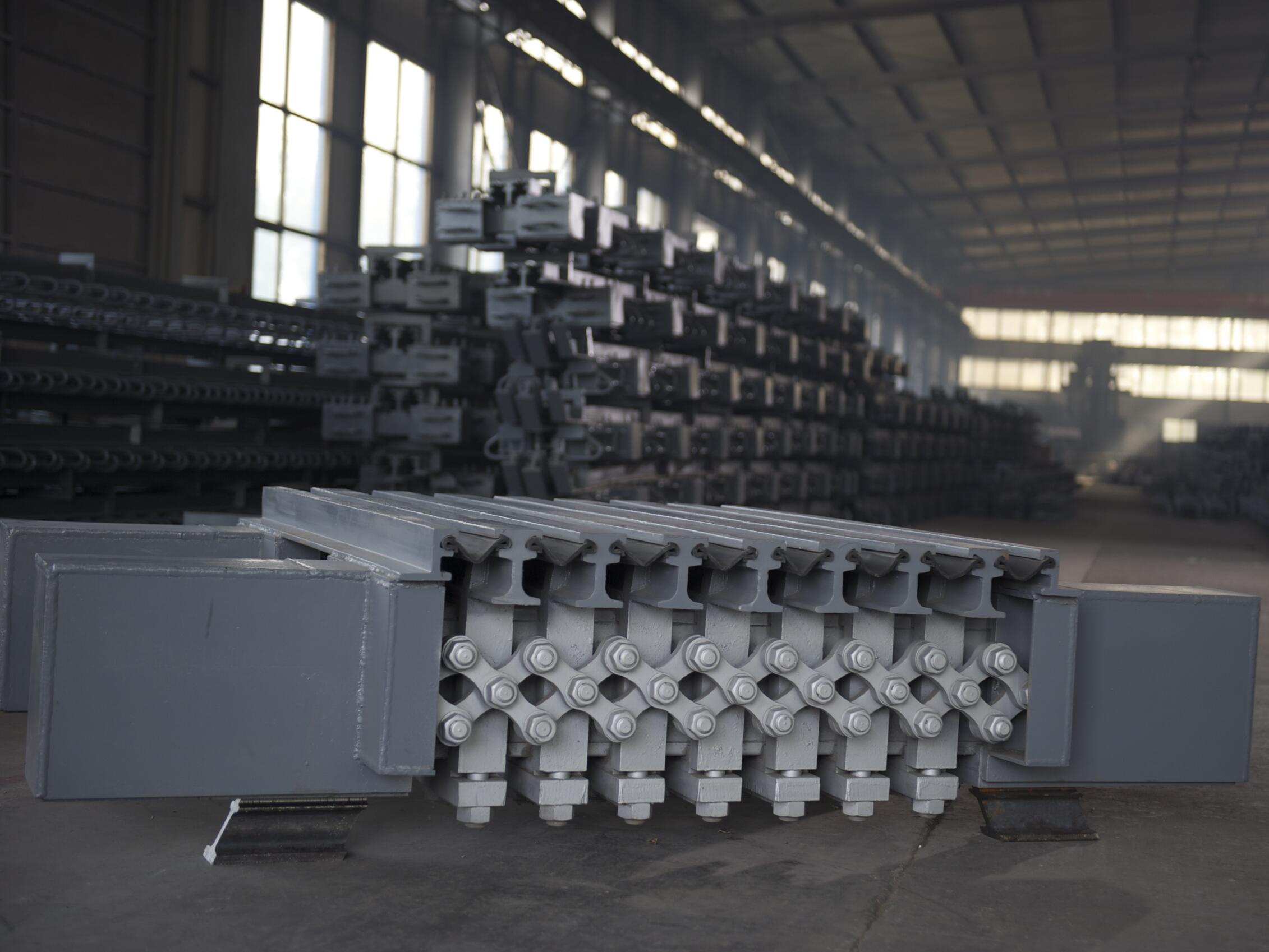
Schematic illustration and actual joint showing the structure of scissor-type equidistance device—rigid connection to equally distribute the movement to each cell of MBJS.
1.5.2 Pre-compressed control springs (control buffers/springs)
Most of such devices are made of polyurethane which has excellent fatigue resistance and resilient ability after millions of cycles. Testing of 300 million load cycles (7 MPa) had been performed and result showed the enhanced polyurethane exhibited no cracks or other failures. Ideally this material has been proven to suit the application for MBJS. The working
principle is apparent. All the buffers are installed in a tandem and together they absorb the incurred move ment. By control the positions of these devices to be right and exact, the equal spacing for each centerbeam opening is achievable.
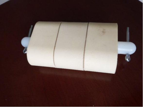
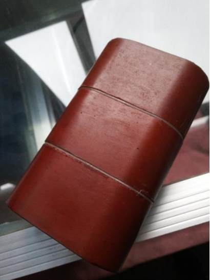
A comparison of polyurethane control spring freshly made and aged
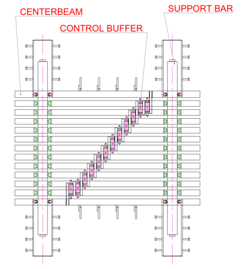
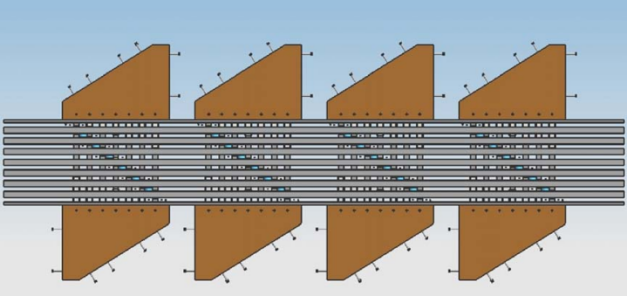
Illustration of a typical layout of control springs attaching to the underside of MBJS
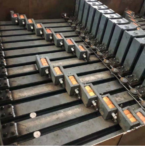
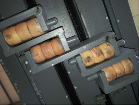
Different layouts of control springs alignment in differently-sized modular expansion joint
(right: control springs behaviour after Opening Movement with Vibration test, OMV test performed at IEC)
Left: control springs layout in a 14-cell MBJS for Hulukou Bridge over Jinsha River, Yunnan, China)
1.5.3 Shear springs (control springs)
The shear springs are placed at the underside of the centerbeams by using retainer frames or plates. They take control of the movements of individual centerbeam and the shear force lure them to work as a single kinematic system. The movements of each centerbeam relative to its neighbors are regulated by control scheme, which are rigidly connected to that centerbeam by steel and to the neighboring centerbeams by connecting frame.
At each edgebeam, the control spring sets are connected to the bridge structure by control boxes (as per below image showing). The elastic gap control system increases the service life of the entire joint by damping the impact loading from traffic impact.
These shear springs are actually specially designed steel-reinforced rubber bearings. Due to the attribute of rubber and the round shape design, the springs can deflect to any direction under shear force. Therefore a good expect of transversal movement and vertical deflection can be realized. When there is large transversal movement request, this design is often considered.
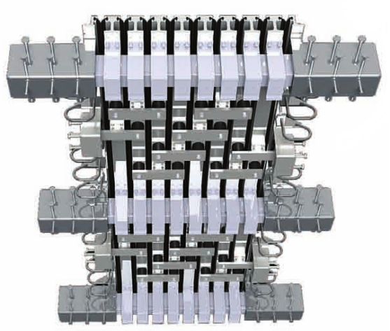
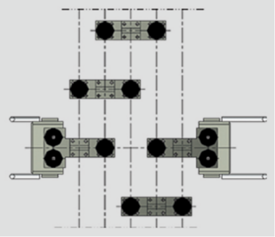
SHEAR SPRINGS LAYOUT (EQUIDISTANCE DEVICES)
1.6 sealing
The uniquely shaped EPDM strip is installed in an extruded cavity in the upper positions of the edgebeam and centerbeam for water tightness purpose. Approved lubricant adhesive prior to inserting of rubber seals is necessary. The sealing element is set below the road surface level which can prevent wheels from contact with them.
Push-out test (SPO) for seals has been performed at IEC aiming to guarantees the bonding between the rubber seal and the mechanically interlocking mechanism---cavities inside the edgebeam and centerbeam.
The rubber seal’s specially designed section allows itself to move in the direction of carriageway without any appreciable strain. Sealing can be replaced from above with a bar when the individual gaps are not less than 30mm. Gap width can be enlarged by moving the beams.
Properties of EPDM
Properties | ASTM Test | required value |
Hardness (Shore A Durometer) | ASTM D2240-04 | 70±5 |
Tensile Strength, Min. (Mpa) | ASTM D412 | 15 |
Ultimate elongation at break, Min. (%) | ASTM D412 | 400 |
Heat Resistance (aged 70 h@100℃) | ||
Max. change in Shore hardness | ASTM D573 | 10 |
Max. change in tensile strength (%) | ASTM D573 | -15 |
Max. change in ultimate elongation (%) | ASTM D573 | -20 |
Compression set (aged 22 h@100℃) (%) | ASTM D395 | 20 |
Ozone resistance (100pphm, 20% strain at 37.7±1℃ 100 h) | ASTM D1149 | no crack |
Brittleness -40℃ | ASTM D746 | no failure |
Oil Swell 70 h@100℃ Max. volume change (%) | ASTM D471 | -5 ~ +10 |
* Neoprene rubber seal is also available upon request.
This data conforms to the ASTMD5973-97(2012)standard specification for elastomeric stripseals with steel locking edge rails used in expansion joint sealing.
2. Movement capacity
2.1 MSB structure
IEC adopts the MSB structure for modular joints which are 2-cell, 3-cell and 4-cell with the convention design to meet the longitudinal movement while limited transversal and vertical movement or rotation is allowed. For larger transversal and vertical movement, Consult IEC expert on project basis.
Special designs based on actual project situation are available. Thus such dimension are subject to change. Consult IEC expert for details.
2.2 SSB structure
For 5-cell and above joints, SSB structure is used, allowing movements and rotation in every direction if necessary. The elastic control system can accommodate large transverse and vertical movement without developing constrain forces.
The maximum movement capacities and the main required dimensions of the block-out (recess) in the bridge structure for the installation of various sizes of expansion joint are provided. Contact IEC expert for more technical information if required. The mentioned dimensions and parameters are based on design provisions in NCHRP Report 402
2.3 skew, footway/parapet treatement
See general info.
2.4 for larger transversal movement--Swivel MBJS
Typically, above-mentioned types of MBJS cater for longitudinal movement as how conventional MBJS function. When it comes to considerable transversal movement, design of MBJS must consider design capable of accommodating both longitudinal and transversal movement. According to AASHTO Bridge Design Specifications, a swivel type of MBJS is introduced for this purpose, which is named as XLF by IEC, as revealed by following image.
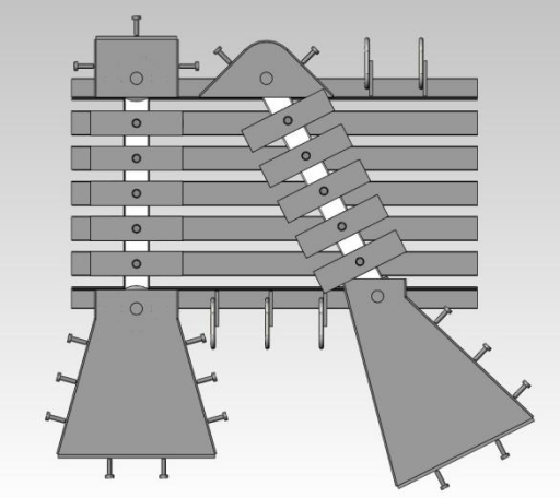
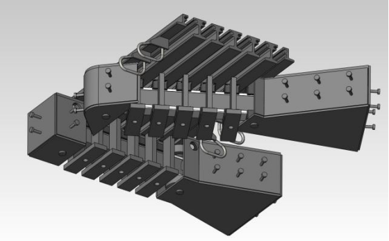
Illustration of swivel MBJS (XLF) to cater for large long. & trans. Movement
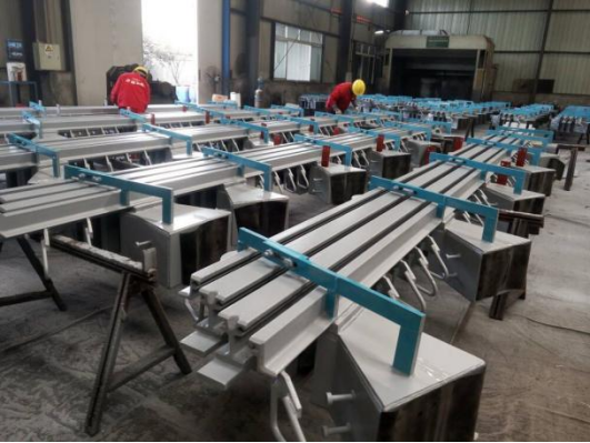
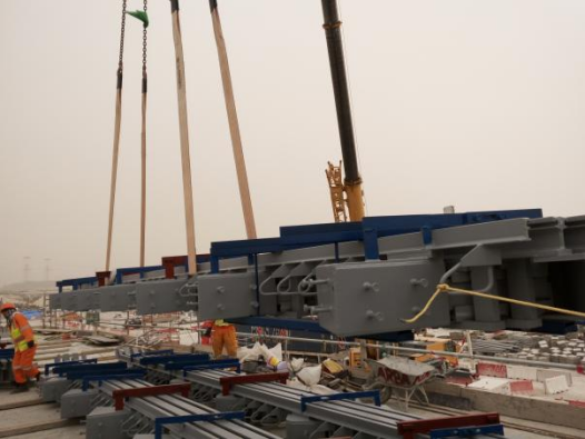 Swivel MBJS under painting at IEC workshop Swivel MBJS lifted prior to being installed
(IEC supplied over 820meters of swivel MBJS as above images for NOH2 project, Qatar, 2018-201
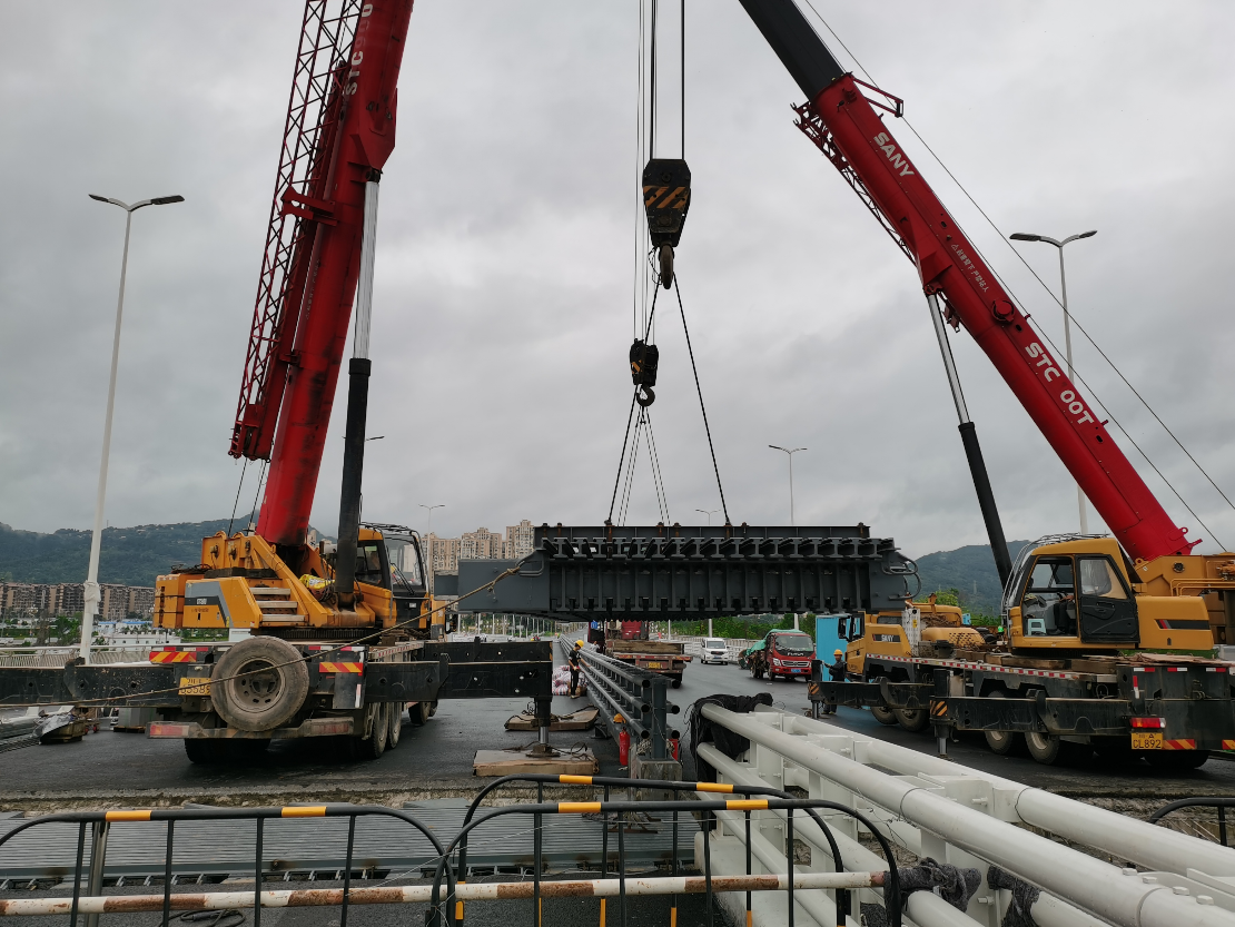
IEC fabricated and installed a 18-cell modular expansion joint for Hantan Bridge, Chengdu in 2021
2.5 for seismic
When considering seismic effect on the MBJS, IES provides solution together with contribution from bridge experts and professionals from Tongji University, Shanghai, to use cable restraint to mitigate the seismic effect as following illustration.
Under normal usage, cable-restrain MBJS functions the same as a regular one, which can accommodate the displacement and rotation of the beam and can also bear and transfer vehicular loads. During an earthquake, when adjacent beams are about to collide, the cable become tensioned to prevent excessive displacement of the beams to avoid collision. When the adjacent beams separate to their maximum displacement, the tensioned cables restrict excessive displacement to prevent beam dislodgement.
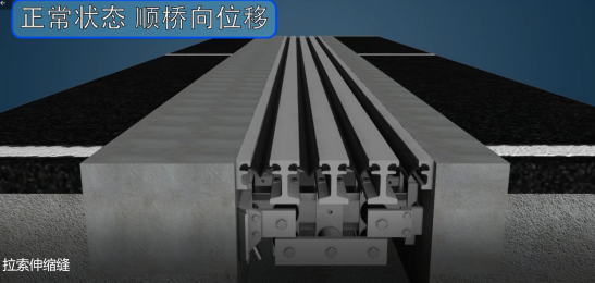
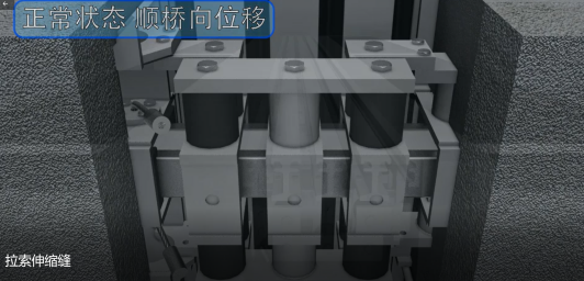
How cable-restrain MBJS works in normal condition
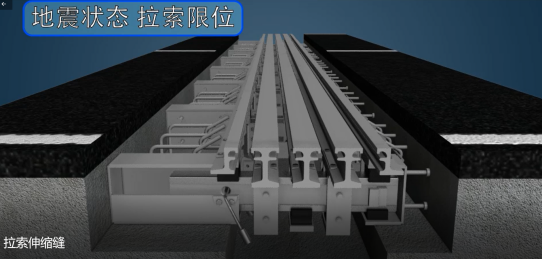
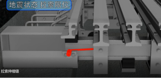
How cable-restrain MBJS works in seismic condition
Consult IEC engineers for details.
3. Materials
ü Centerbeams, edgebeams, support bars of Q355B steel typically (equals to S355JR steel, or ASTM A709 Gr.50); Q345D is also available upon request (equals to S355J2);
ü Support box plates, keeper plates, anchorage of Q255B steel (S235 steel, or ASTM A709 Gr.36);
ü Sealing element of EPDM normally; Neoprene is available as well;
ü Control spring, compression spring and sliding bearing of steel-reinforced elastomeric bearings with virgin PTFE, or polyurethane.
4. Quality assurance
4.1 Quality management system
■ ISO 9001:2015
4.2 Welding
■ EN ISO 9601
4.3 CE certification
■ EN 1337-3 for Elastomeric Laminated Bearings, same method to control quality for rubber seal, elastomeric parts for the MBJS
4.4 Related certificate
■ Environmental Management System ISO 14001:2004;
■ Occupational Health and Safety Management System OHSAS 18001:2007;
■ Calibration and Measurement Certificate;
■ China National Accreditation Service for Conformity Assessment (CNAS) for IEC laboratory.
4.5 Test report (according to AASHTO LRFD Bridge Construction Specification)
■ Opening Movement with Vibration (OMV);
■ Seal Push-out (SPO);
■ Fatigue (in preparation);
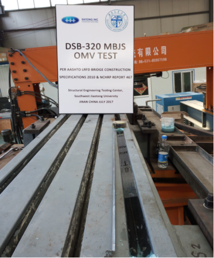
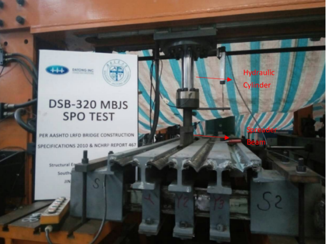
OMV and SPO test setup for IEC’s modular expansion joint according to AASHTO LRFD Bridge Construction Specifications and NCHRP Report 467
5. Technical Submittals and Services
■ Calculations (mostly based on AASHTO; other specs are available upon request);
■ Design shop drawings;
■ Method Statement;
■ Risk Assessment of expansion joint installation;
■ Maintenance and Replacement Manual;
■ Storage, Lifting and Handling;
■ Onsite installation assistance and supervision;
6. Installation, maintenance and replacement
Consult IEC for details.