TWINSA in one minute
A bridge is safe only while its strength stays above the force inside it. Strength gets inspected, tested and sensored — the force state is taken from the design drawings and assumed.
TWINSA's Smart Adapter makes a bearing's force readable in place, under load — the calibration that standard practice says is impossible, because a working bearing can never be unloaded and sent back to a lab. Validated by the national metrology institute at under 3.5 % error, and confirmed as a world first by an independent novelty search (STiRI, 2024).
The measured forces feed a digital twin that works out where the load really sits. The same hardware can then adjust the force and re-measure to prove the result. Measure → understand → adjust → verify — a loop, not a one-off inspection.
Decisions stop being "add material to be safe" and become "manage the measured force" — the same safety and service life, for less capital, less maintenance and less carbon.
The nine chapters below tell the full technical story. Every claim is measured, filmed, or on the public record.
Safety has two terms — how strong the bridge is, and the force it actually carries. Until now, only the first was ever measured.
One half of the safety equation has always been assumed, never measured: a load-bearing constraint can never be unloaded to calibrate it, so the force locked inside the structure stays whatever design day assumed. Inspection, load testing and SHM keep sharpening resistance R; demand S they cannot see. TWINSA breaks that limit — the boundary force becomes metrologically traceable, in service and under load.
| Inspection & NDE | Load testing | SHM | |
|---|---|---|---|
| R — capacity / condition | ✓ | ✓ | ✓ |
| S — actual force state | — | — | — |
Three families of assessment evidence — all of them update R. The S row stays empty.
β = (μR − μS) / √(σR² + σS²)
Safety margin over combined uncertainty. Every term on the R side can be measured; μS and σS never could — until the boundary force became measurable. Then one term also becomes adjustable.
Assessment measures the response and updates R. Because a structural constraint is never unloaded, S is inherited from design — an assumption no inspection can verify. Two bridges with identical monitoring records can hold very different real margins.
The boundary force itself becomes measured — traceable, in service, under load, with no prior art (STiRI, 2024). S stops being assumed and becomes a measured input; because the bearing's own height is an actuator, it also becomes adjustable. Reliability stops being assumed and becomes managed.

Not a one-off inspection: measure the force, understand the structure, adjust it, and prove the result — as a working loop.
Boundary force at bearings, cables and bolts — metrologically traceable, not a model assumption.
Joint inversion recovers stiffness, the hidden erection state, and the drivers behind S.
The bearing's own height is the actuator; a target force state defines the in-situ move.
Re-measurement against the target; the new force state becomes the baseline.
Verification feeds back — the model and the baseline are updated, then measured again.
The device that makes a bearing’s force readable — and adjustable — in place, under load, with the bridge open to traffic.
The Smart Adapter is a load-path mechanical system installed at the constraint. Through its wedge pair, the working load develops a horizontal component read by an internal sensor; during in-situ calibration, hydraulic jacks push the wedges to the friction-reverse state, so load and effective friction coefficient are solved together — calibration without unloading, without moving the structure. The same through-load sensing extends from bearings to cables and bolts.

| Capacity range | 5 – 150,000 kN; fits pot, spherical, elastomeric and friction-pendulum bearings |
| Measurement accuracy | overall error < 5 % worst case; repeatability < 2 % |
| In-situ calibration | error < 3.5 %, validated at a national metrology institute; re-calibration capability retained after long-term compression |
| Durability | 2 million cycles of railway dynamic-load fatigue testing |
| Adjustment | control sensitivity 0.005 mm (laboratory); 5 – 10 mm per stroke, unlimited travel with shim plates |
| Host bearing | load, rotation and displacement functions unimpaired |
The proven core: measurement-and-control bearings with in-situ calibration, from 5 to 150,000 kN, in service on bridges today. The Smart Adapter reads the boundary force inside the host bearing, and friction-reverse calibration re-establishes the reading–force relation under load — the measurement stays traceable for as long as the bearing carries the bridge.
Cable and tension systems: the same boundary-force logic applied to stay and anchor forces. The tension a cable actually carries — measured, not the value assumed on design day — feeds the digital twin's demand side, so the S curve is put on measured ground for the tension members as well.
Bolted connections: preload is set precisely at installation, then assumed to hold — but vibration and service loads change it, and a torque record cannot say by how much. Measuring the clamped force directly under load replaces that assumption with a reading, so re-tensioning follows measured need rather than the calendar.
Not a lab concept: a viaduct in service, every support line instrumented, readings checked against reality for two years.
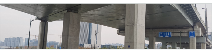
A three-span, skewed, variable-section continuous steel box-girder viaduct carries twelve TWINSA measurement-and-control bearings — complete boundary-force coverage at every support line, monitored continuously in service for two years. The force state that assessment normally assumes is here measured directly — and what it reveals was invisible to inspection.

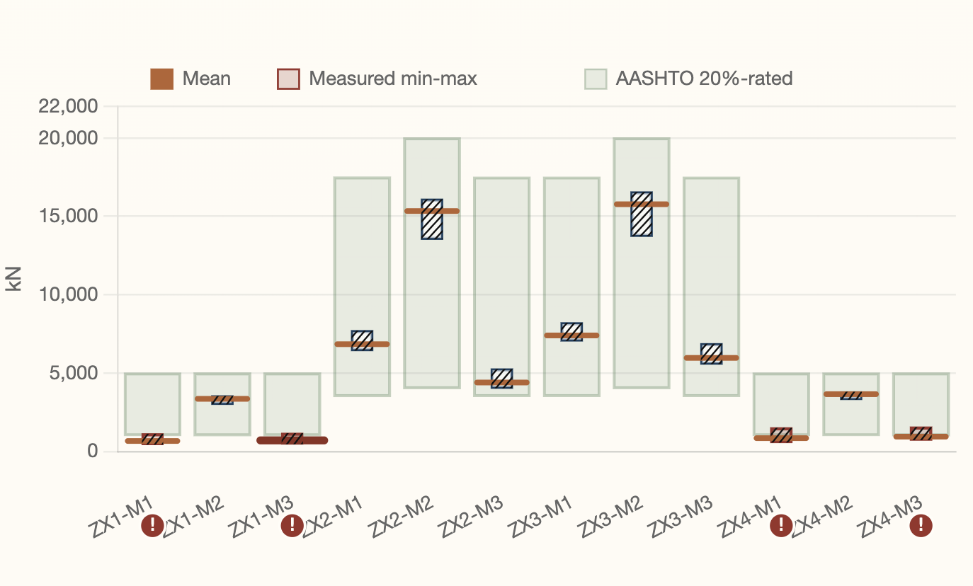

The reactions were lopsided from day one. At pier ZX1 the centre bearing carries ≈ 3,450 kN — about seven times each side bearing (≈ 450 kN). Four of the twelve bearings sit far from their rated share of load: a locked-in state, invisible to inspection, plain in the measured reactions.
Two shapes explain the same reactions — the measured elevation decides. Read as support movement, the reactions at pier ZX1 say the centre support sits ≈ 4 mm high (force-equivalent). But the supports are measured level — so the real cause is the girder's own zero-stress shape, sagging by that amount and locked in at erection. Joint inversion recovers the full identified state — the measured force, the level elevation, and the stiffness the structure really has (seven girder and crossbeam groups within ±25 % of design, identifiability 52–94 %) — and quantifies the zero-stress shape to the millimetre.

The model reproduces every channel. The recovered excitation, pushed through the recovered structure, reproduces all twelve measured reactions with NSE ≥ 0.94 — a forward check that makes the inversion falsifiable, not a curve fit.
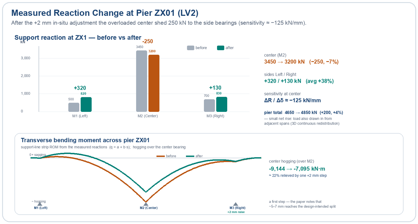
A +2 mm move rebalanced the pier. Guided by the identified state, a single +2 mm in-situ height adjustment shed 250 kN (−7 %) from the overloaded centre bearing onto the side bearings (+320 / +130 kN) and relieved the transverse hogging moment by ≈ 22 % — sensitivity ≈ −125 kN/mm, measured, not simulated.
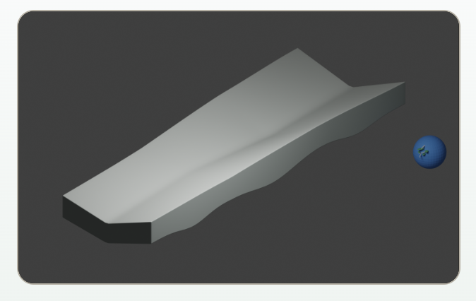
Joint inversion turns twelve reaction time histories into a physical explanation: the stiffness the structure really has, the shape it was locked into at erection, and the drivers that move the force state day by day. Each claim is pushed back through the model and checked against the data — which is what separates an identification from a curve fit.

In December the model's residuals showed a step change at one support line — the field move of finding 4 opposite had not yet been reported to the modelling side.
Re-anchored on the measured data, the twin located an edge-bearing constraint change at pier ZX1.
The field log later showed a +2.00 mm lift at exactly the bearing the model singled out; the other two bearings on that line saw no field action.


What measurement changed in practice: a support corrected by force, not by eye — and the model updated to match.
For a century the rating carried S as an assumption from design day. Once S is measured, not assumed, the same measurement moves one rating down and one rating up — and that asymmetry is the point: a measured force replaces blanket conservatism with located knowledge, in both directions.
98.2 % → 37.2 %
The assumed force state was over-conservative; measured, the reserve is real and can be used.
26.8 % → 45.1 %
Capacity remains ample, but the measured force distribution differs from the design assumption and now sits on the maintenance radar.
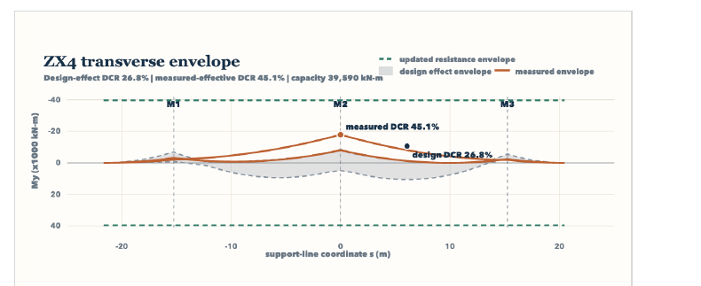

Neither correction was knowable while S stayed assumed. An owner who only updates R keeps paying for conservatism where the structure is strong — and stays blind where the structure quietly moved. With S measured, the rating stops being inherited and becomes a managed quantity.
The method is becoming the rulebook — a national metrology specification and product standards are in the pipeline.
Force calibration, as standardized (ASTM E74 · ISO 376), assumes an unloaded device.
A load-bearing constraint is never unloaded. It carries the bridge for decades and cannot go back to the laboratory — so without an in-situ method, the traceability chain breaks on the day of installation, and that is exactly why S stayed an assumption for a century. TWINSA's friction-reverse calibration re-establishes the reading–force relation under load, without unloading, without moving the bearing or changing its loading state — with no prior art (STiRI, 2024).


China’s national metrology specification, Calibration Specification of Intelligent Force-Measuring Bridge Bearings (JJF, under review), now defines in-situ calibration: establishing the reading–force relation without changing the bearing’s position or loading state. IEC has also drafted the accompanying product and construction-method specifications.


| National metrology specification | Calibration Specification of Intelligent Force-Measuring Bridge Bearings (JJF, under review) — defines in-situ calibration; lab validation method included |
| Product & construction specifications | drafted by IEC alongside the metrology text; spherical-bearing product standard at approval-draft stage |
| International track | IABSE TG 6.8 works toward extending ISO 376 force-metrology practice to structural constraints |
| In-situ calibration error | < 3.5 % — worst case: maximum rotation + maximum horizontal force; validated at a national metrology institute |
| Overall measurement error | < 5 % worst case; repeatability < 2 % |
| Durability | 2 million railway dynamic-load fatigue cycles; re-calibration capability retained after long-term compression |
Everything lands on one screen: the live force state, the model behind it, and the deviations that matter.
Once the boundary force is measured, not assumed, an owner needs one place to act on it. TWINSA's field hardware feeds a single platform: BearingSmart Cloud holds the calibrated baseline, runs the mechanical model, and turns raw reaction channels into the measured demand S that reliability calculations always needed and never had.

| Calibrated baseline | the measured force state, traceable to in-situ calibration — the reference every later reading is judged against |
| Live separation | constant offset (erection condition) split from daily thermal oscillation, so drift is visible early |
| Rating inputs | measured demand S feeding DCR and β directly, in place of assumed load distribution |
| Intervention record | before/after force states for every adjustment — evidence, not recollection |

Bearings first — then cables and bolts. New bridges and old, in construction and in service.
Bearings arrive as measurement-and-control components; the erection force state is documented from the first day, so the as-built condition never becomes a guess.
Existing bearings are retrofitted with Smart Adapters; the measured force state re-anchors ratings that previously inherited design assumptions.
Smart wedge jacking: ultra-low profile, self-locking, zero traffic disruption — and the structural force is calibrated during the works instead of assumed afterwards.
Rotation spherical bearings and heavy components are installed, adjusted and later extracted under force control rather than geometry alone.

A level deck is not proof of a healthy force state — geometry can look normal while the structure is already suffering. Conventional shimming and re-jacking level the geometry blind to force, with no baseline to judge the result. A TWINSA adjustment is force-governed: measure, optimize the force state, re-measure, confirm — the same measured quantity that reliability now manages instead of assumes.

Making the constraint force measurable and adjustable is only useful if the same wedge mechanics hold at real scale. They do — from 5 kN to 150,000 kN. Three operations mark out the envelope, each with the load kept on.


An international peer group is now writing the global agenda around measured force — chaired from this work.
Once demand is measured rather than assumed, the margins built to cover the unknown are no longer needed — the same safety and service life for far less capital, maintenance and carbon.
Design to measured demand instead of worst-case assumption — carry less excess steel and concrete.
Fix the force state by a small adjustment, not by adding capacity — a fraction of the cost, little downtime.
Catch and correct the force state before it becomes damage — defer or avoid replacement.
Less material, fewer retrofits, longer life — fewer tonnes of embodied and operational CO₂.
Lower capital cost, lower lifecycle cost, lower carbon — all of it follows from one change: reliability stops being assumed and becomes a managed quantity, and that capability keeps paying back across the asset's life.
New-build or retrofit.
Calibrated baseline, recovered state.
Measured DCR / β, located priorities.
Force-governed intervention, re-measured evidence.
Deliverables at every step: a calibrated baseline, measured rating inputs, and a before/after record of every intervention.
Under the old paradigm the safety index β was inherited from the code's assumed load factors. Once R is updated by measurement and the demand S is measured rather than assumed, β stops being a design-day number and becomes something the owner tracks and manages.

Make the constraint force measurable, assess the real state, and let the structure adapt.
IEC convenes and chairs IABSE Task Group 6.8, Mechanical Adaptivity for Sustainable Structural Lifecycle (Commission 6). Its programme follows the verbs that drive TWINSA — measure the constraint force, assess the real state, let the structure adapt.


 Khalid MosalamTaisei Professor of Civil Engineering, UC Berkeley; Director, Pacific Earthquake Engineering Research Center (PEER). Authority in large-scale structural testing and hybrid simulation.TestingSeismic
 Paolo GardoniAlfredo H. Ang Family Professor, University of Illinois Urbana-Champaign; Director, MAE Center; Editor-in-Chief, Reliability Engineering & System Safety. Leading scholar in risk, reliability and resilience of infrastructure.ReliabilityRisk
 Bruno BriseghellaDistinguished Professor, College of Civil Engineering, Fuzhou University; Member, European Academy of Sciences; President, International Association of Jointless Bridges.BridgeJointless
 Wang TaoProfessor, Institute of Engineering Mechanics, China Earthquake Administration. Seismic engineering, large-scale shaking-table and hybrid testing.Seismic
 Wang DaleiProfessor & Head, Department of Bridge Engineering, Tongji University. Bridge structural health monitoring (SHM) and intelligent operation & maintenance of long-span bridges.BridgeSHM
 Xia YeProfessor, Tongji University. Bridge SHM, digital twins and AI-assisted condition assessment of bridges.BridgeSHM
 Sreenivas AlampalliCEO, Alampalli Engineering, PLLC; Founding President, IABMAS-US; former Director, Structures Management Bureau, NYSDOT. ASCE Distinguished Member; over 30 years leading bridge inspection, load testing and structural health monitoring.BridgeSHM
 Chen XiaohuPresident, T.Y. Lin International China; Chongqing Engineering Survey & Design Master; U.S.-licensed structural engineer (Ph.D., Maryland; Tsinghua). Led the design of Chongqing’s Dongshuimen and Qiansimen twin river bridges; Eisenhower Fellow.BridgeDesign
 Tzyy Wooi TehDirector, H&T Consulting Engineers Group, Malaysia. Structural and bridge engineering practice across Malaysia and Southeast Asia.BridgeDesign
 Deng YuChief Engineer & GM of Bridge Division, T.Y. Lin International China. Xiang Hai-Fan Outstanding Young Bridge Engineer Award; led design of the Macau Bridge.BridgeDesign
 Deng Qing’erBridge Chief Engineer, Tongji Architectural Design (Group) (TJAD). Over 30 years in major-bridge design — Donghai Bridge and Shanghai Minpu Bridge among them.BridgeDesign
 Feng YuanNational Engineering Survey & Design Master; Chief Engineer, China Southwest Architectural Design & Research Institute (CSWADI). Long-span spatial structures — stadiums, airports and cultural landmarks.BuildingLong-span
 Zhou DingsongDeputy Chief Engineer, CSWADI. Seismic design of building structures; ductility-demand-spectrum research with Academician Lü Xilin.BuildingSeismic
 Chen LieSichuan Engineering Design Master; former Deputy Chief Engineer, China Railway 2nd Design Institute. High-speed-rail bridges and seismic isolation.RailwayDesign
 Zhang ShenglinGeneral Manager, Guizhou Transportation Investment R&D Co.; Deputy to the National People’s Congress. Construction technology leader of the Pingtang Bridge and the Huajiang Grand Canyon Bridge — the world’s highest; National Model Worker (2020).BridgeConstruction
 Guo HuiDeputy Director, Bridge Engineering Division, China Academy of Railway Sciences (CARS). Railway bridge assessment, monitoring and dynamic performance evaluation.RailwayBridge
 Liang XinPh.D. in structural mechanics, University of Cambridge; IEC structural lead. Landmark steel structures and super high-rise design.BuildingSteel
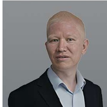 Wang JianmingPh.D.; Technology & R&D lead, IEC. Standards drafting, R&D management and engineering project delivery.R&DStandards
Metrologically traceable constraint force, traceable to a reference — advancing ISO 376 for force sensors.
Evidence-based force-state evaluation — the measured demand enters the LRFD safety check directly.
Active, data-driven force redistribution — intervene to extend service life, avoid premature replacement.
Live system: twinsa.bearingsmart.cn — measured force states, open for owners and partners.